
Measurement Tutorials
Educational guides for VNA calibration, active circuit measurements, radar demos, and EDA workflows.
RF/mmWave Video Collection
A curated collection of educational videos spanning high-frequency hardware measurements.
Antenna characterization
60GHz Radar Antenna Pattern Measurement
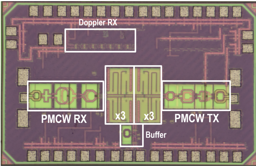
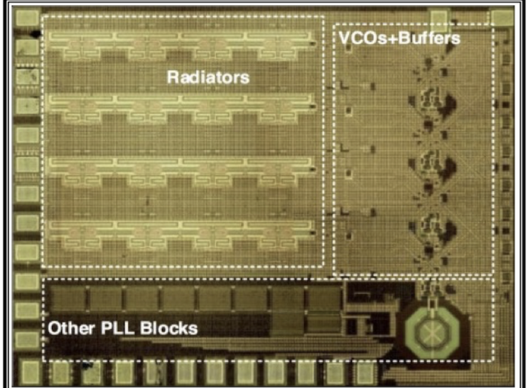
This demonstration shows the measurement of an antenna radiation pattern for a 60GHz phase-locked FMCW radar transceiver (ESSCIRC & JSSC published).
Test Setup & Equipment
- Device Under Test (DUT)
- 49-63 GHz FMCW Radar Transceiver with packaged antennas.
- Reference Antenna
- Horn antenna calibrated for V-band.
- Mechanical Stage
- High-precision rotary stage for angle sweeping.
- Instrumentation
- Spectrum Analyzer with V-band harmonic mixer for power detection.
System-level testing
ICLEGEND MICRO XenP202TT 24GHz Radar Demo
A real-world performance demonstration of a 24GHz radar module tracking physical targets. This showcases how raw RF signals are processed into actionable tracking data in real-time.
Measurement Objectives
- Target Emulation
- Using a metallic corner reflector to provide a reliable, high RCS (Radar Cross Section) target.
- Distance Resolution
- Verifying the range accuracy extracted from the FMCW beat frequency (IF).
- 1D Angle Measurement
- Evaluating the Field of View (FOV) and Angle of Arrival (AoA) estimation using RX antenna arrays.
Active circuits
3.1GHz - 4.66GHz VCO Measurement
Validating the performance of a wideband Voltage-Controlled Oscillator (VCO) intended for a TCAS-I paper submission. This type of measurement is critical for characterizing the purity of the local oscillator (LO) signal, verifying both phase noise and output power under room temperature conditions.
Key Parameters Extracted
- Tuning Range
- Sweeping the control voltage (Vtune) to verify the 3.1 - 4.66 GHz coverage.
- Phase Noise
- Measured typically at a 1MHz offset from the carrier to determine oscillator spectral purity.
- Output Power
- Ensuring sufficient LO drive strength across the entire tuning band.
Antenna PCB integration
Export HFSS Antenna Design to KiCad
A crucial step in hardware realization: taking a validated 3D electromagnetic antenna simulation and integrating it onto a PCB structure. This bridges the gap between EM physics and physical PCB fabrication.
Integration Timeline
- 1
HFSS Export: Exporting the 2D layout geometry (usually DXF or GDSII format).
- 2
KiCad Import: Importing the geometry to create a custom Footprint matching the exact EM simulation dimensions.
- 3
Gerber Generation: Generating the standardized RS-274X Gerber and Drill files required by PCB fabs (e.g., JLCPCB, PCBWay).